An introduction to computer networks - part 2
The next development in Ethernet technology was the star layout, even though the network is still a logical bus.
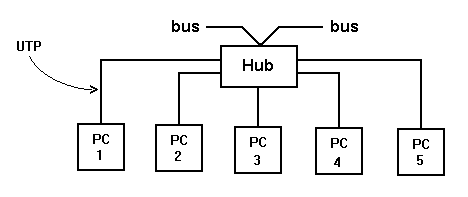
Known as 10 Base -T, this layout uses hubs from which Unscreened Twisted Pair cables are fed out, one to each PC.

This layout allows the UTP cable to be concealed behind walls and skirting boards, coming to the surface at wall boxes, with sockets, similar to the arrangement for telephones. The PC is connected to the wall socket using a length of flexible UTP, just like the cord from a telephone.
Buildings can be saturation wired, with wall sockets at convenient places. PC`s can then be plugged into and out of the network by unskilled workers at will, without affecting the operation of the rest of the network.
There are a number of different types of hubs, which offer different characteristics.
In the first type, inside the hub, although there will be signal processing, in logical terms, each port to which UTP is connected is connected to all other ports, and so the logical result is that a hub is still part of a bus, with all PC`s connected to all other PC`s.
So if PC1 sends data to PC4, all the PC`s connected to the hub, and the rest of the network "see " the data packet, even though they ignore it, as only PC 4 is the intended recipient.
The second type of hub is logically passive, like the first type, but it contains more signal processing and amplification - it therefore acts like a repeater, and can be used to extend the geographical spread of the network by interconnecting LAN segments.

More recent developments in Ethernet network design have removed the situation whereby all PC`s and all segments "see" all the signals put on the bus by any source.
As applications such as word processing, graphics, and DTP have developed, they are producing much larger files, which have to be shifted around the network.
So, for example, whereas an early word processor would produce a letter in say 1 k of data, a modern word processor / DTP package produces a basic text document in a file of around 20K, due to all the formatting information.
And graphics files can easily add another 100 K of data for each picture.
The result is that networks became overloaded, and in Ethernet, that means the network simply grinds to a halt.
As network technology has evolved, a number of solutions have been developed.
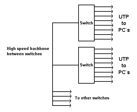
One of them is the third type of hub - known as a fast switching hub, or switch.
In this type of hub, the ports are not connected together - each port acts as a node, in that when the port is sent a data packet from the PC that is attached to it, the switch reads the address of the destination PC, and routes the packet to the appropriate port for onward transmission to the PC.
So if PC 1 sends data to PC4, the switch routes the data packet only to port 4.
And if PC 5 sends data to PC 2, the switch routes the data packet only to port 2.
And these two connections can happen at the same time.
This technique of switching according to destination addresses is known as packet filtering.
In performing this function, the switch actually acts as a node, in that the switch accepts responsibility for the packet - the sending PC thinks that the packet has been successfully transmitted, even though it has only been received by the switch. The switch becomes responsible for the onward transmission of the packet to its intended destination.
Fast switching hubs can act in two ways :-
Store and forward switches - the whole data packet is stored in memory within the switch, checked for errors, and then onward transmitted.
Cut through switches - the switch only stores enough of the data packet to be able to read the destination address - as soon as it knows this, the data packet is routed and sent on its way.
Cut through switches have a much shorter propagation delay time for the data packet, but store and forward switches have the advantages that they can dump corrupt packets, so that network time is not wasted, and they can also send on the data packet at a different rate from that at which it arrived - so a store and forward switch can interconnect the 10 Base - T network with a high speed backbone, for example, a fibre optic based system, ATM, or high speed ethernet.

© 1998 Ron Turner
Go to part 3 - bridges
Return to network home page