An introduction to computer networks - Part 1
There are three basic topologies used in LAN`s - these are
Bus
Star
Ring
Most LAN`s, no matter how large or complicated use these basic building blocks to interconnect PC`s.
Each topology has its own advantages and disadvantages.
However the type that has until quite recently been used in the highest number of installations is the bus topology.
The Bus Topology :-
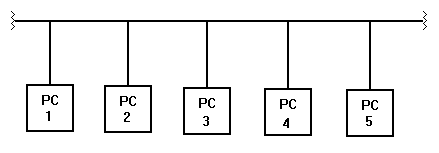
In its basic form, this is a long length of cable, off which "hangs" each PC, via its own connection to the bus.

At each end of the bus there is a termination resistor, whose value of 50 ohms matches the characteristic impedance of the cable used for the bus, and thus there are no signal reflections off the ends of the cable.
There are international standards defining the physical type of cable and the layout of the network - two of these are IEEE 802.3 and Ethernet - these two standards are very similar, but there are some small differences.
Ethernet was the first, and was created by Xerox - it ran at a speed of 2.94Mb/s. This was followed by the international standard IEEE 802.3 - this runs at 10 Mb/s. Ethernet now also runs at 10Mb/s. The difference between them is not in the physical layout, but in the construction of the data packet.
Ethernet has become the generic name for this kind of bus based network topology.
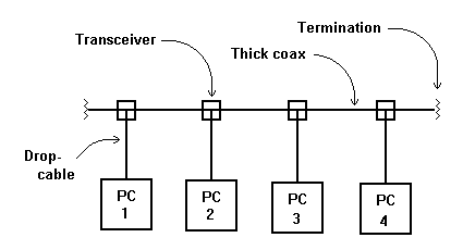
The original IEEE 802.3 standard defined what is now known as thick Ethernet - this utilises a 50 ohm coaxial cable with diameter of approximately 0.5" as the bus cable.
Another name for thick Ethernet is 10 Base-5.
Connections to each PC were made via taps in the cable - the reliable way was to cut the cable and put in a proper joint, the quick way was to use Vampire Taps, which were spiked clamps secured around the cable - the spike pierced through the outer layers of the coax and made contact with the central conductor. Unfortunately, it was quite easy to either miss the central conductor with the spike, and so have no connection, or to actually cut the central conductor with the spike, and thus have no network.
Which ever method was used to tap the cable, at the tapping point a device called a Transceiver or Media Attachment Unit was mounted - from this a secondary drop cable connects to the PC.

A later development in Ethernet network design was the Thin ethernet.
Known as 10 Base - 2, this utilises a thinner coaxial cable such as RG 58, still with an impedance of 50 ohms, but this cable is flexible, and is snaked around from PC to PC.
Connections to the PC`s are made via BNC T - pieces fitted into the bus cable.
Minimum interference to signal flow will be achieved if the bus cable is taken right to the Network Interface Card within each PC, and the T - piece mounted directly on to the NIC.

The standard for Thin ethernet actually allows for a drop cable between the T - piece in the bus and the NIC in the PC, the maximum length of this cable being 1.6 feet.
However, strictly speaking, the use of a drop cable will actually produce an impedance mis-match at the T - junction, with some reflections being caused.
Although more easily handled than thick ethernet, thin ethernet does have the disadvantage that the coaxial cable bus has to snake around the work environment from PC to PC. As such it is easily damaged, and as there is a T - piece connector in the bus at each PC, the bus is easily broken by accidentally disconnecting one of the joints at any T - piece.
Another disadvantage of thin ethernet compared to thick ethernet is the maximum length of a LAN segment.
With thick ethernet, segments can be up to 500 metres long, however with thin ethernet, segments can only be up to 185 metres long.
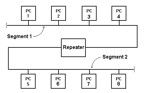
This problem can be overcome to a certain extent by the use of repeaters to connect the ends of individual segments together, to form extended LAN`s.

A repeater contains a bi-directional signal processor and amplifier - it has no logical effect, all signals arriving at one port of the repeater are fed through the to other port, so all the interconnected segments see every signal launched by any PC attached to any segment.
This is known as packet repeating.
There are limits within the standards for thin ethernet for the use of repeaters - there can be a maximum of five segments in a chain, making a maximum LAN length of 5 x 185 metres, or 925 metres.
For thick ethernet, again there can be a maximum of five segments, making a total length of 5 x 500 metres, or 2500 metres.
Note that on thin ethernet, there can be up to 30 PC`s on each segment; however on thick ethernet only three of the segments can have PC`s attached - the other two must just be used for extending the network.
However on thick ethernet, there can be up to 100 PC`s on each of those three segments.
© 1998 Ron Turner
Go to part 2 - hubs and switches
Return to network home page