VLAN`s
Introduction
One of the add on features of some switches is the provision of VLAN`s, or Virtual Networks.
A VLAN is a method of splitting up a physical network segment into a number of logical network segments.
The result is that computers or hosts attached to one VLAN can only "see" the other computers or hosts in the same VLAN, and not those in other VLAN`s.
What VLAN`s look like
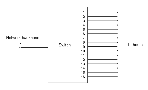
A switch providing say 3 VLAN`s would, at the physical level, look like any other switch, ie,

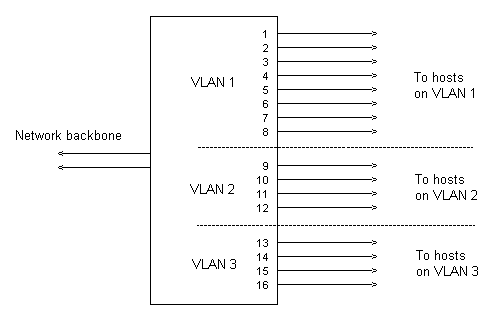
However at the logical level, it would look like

The 3 sections defined as VLAN`s are functionally separate.
Data traffic between hosts connected to ports in the same VLAN is just as normal. The switch sets up a temporary exclusive connection between the two ports which lasts only as long as the transmission time of the data packet, and no other port, and hence no other hosts, see the data packet.
Now it is of course the primary function of switches to provide virtual connections between two hosts, so that data flow between these two hosts is isolated from all other hosts.
However a considerable percentage of data traffic on any network segment is broadcast traffic, ie, a host sends out some form of data without a recipient address, and it is the duty of a switch to distribute this across the whole network segment.
For a switch operating without VLAN`s being set up, this would mean that every port on the switch would see the broadcast trafic, and pass it on the hosts connected to the ports.
However, because the switch now has functionally separate sections, the VLAN`s contain this broadcast traffic, so that it is only sent to hosts within the respective VLAN, hosts on other VLANs don`t see it.
So now broadcast traffic within VLAN 1 will only be distributed to ports 1 - 8, ports in the other VLAN`s will not see it.
Likewise, broadcast traffic within VLAN 2 and VLAN 3 will only be distributed to the ports within these respective VLAN`s.
The setting up of VLAN`s has therefore created what some texts refer to as "broadcast domains".
Some effects of VLAN`s
It is important to note that the splitting up into VLAN`s is done by specifying to which VLAN each switch port is assigned.
The host does not neccessarily know it is part of a VLAN - the assignment is done through the switch port.
This has two immediate effects
If a host is moved from one part of the physical network segment to another part, it may end up being connected to a port in a different VLAN - so the switch will have to be reprogrammed. This will cause a substantial workload if the site has several VLAN`s and a lot of end user workstations.
-
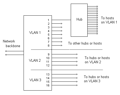
Instead of connecting a host such as a computer onto a switch port, a hub can be connected, and then all the ports on the hub are on the same VLAN as the switch port.
This is one method by which a VLAN can be made large enough to accomodate, say, 500 hosts.

Extending VLAN`s
The use of hubs is one way of increasing the size of a VLAN, but is really only suitable where all the hosts are in the same physical location, eg, on one floor of an office block, or in one medium sized building on a campus which has several separate buildings.
If it is required to extend a VLAN so that it includes hosts that are dispersed in different parts of the site, then other methods are required.
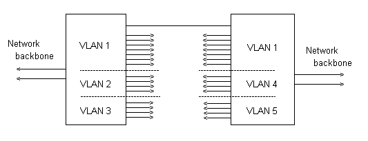
The first method which can be used is to connect switches together through one port in each switch, and set up these ports all to be in the same VLAN.

The drawing shows that in each switch, port 1 has been assigned to VLAN 1.
However this is not realy a recommended method -
it uses up ports on each switch, and if there are several switches which have to be connected together in this way, then another pair of ports is used up for each additional switch
there has to be installed a separate cable for each pair of switches that have to be linked in this way - if there is considerable geographical separation between the switches, then this can be a real problem
A much better solution is to use the already installed network backbone to transmit information about VLAN`s to all the switches in the network. And it can be done, except there are a few problems with it - to transmit the information there has to be a protocol that all the switches understand.
Such protocols do exist, but unfortunately, most of them are manufacturer specific, and are not understood by switches from other manufacturers.
3Com developed VLT ( virtual LAN trunk )
Cisco developed ISL ( inter-switch link ) for use on fast-ethernet, and 802.10 for use on FDDI
Fortunately common sense eventually prevailed, and an agreed standard emerged. This is known as 802.1q
It`s basic method of working is to add to the headers of data packets a section which defines the VLAN. The section is known as a tag.
This extended packet can then be transmitted like any other packet over the network backbone, and the receiving switch extracts the tag, and hence the VLAN information.
It is essential that both the sending switch and the receiving switch are set up to understand tagged packets. If a tagged packet is sent to a device that does not understand tagging, it will see the extra section in the header as wrong information, with possible catastrophic results.
802.1q is not yet in universal use, but it is gaining acceptance. Generaly speaking, 802.1q can not co-exist with VLT or ISL in switches, so there has to be a big bang switch over from one protocol to the other across the whole of a network.
There is also now emerging some leading edge workstations that are 802.1q compatible, so the tagging can start right at the hosts.
© 2001 Ron Turner
Return to the index page